December 20th, 2019 - Optical axis input interface
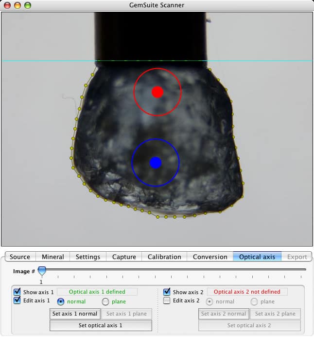
This time I think I have a proper interface to define the optical axis' of anisotropic materials, here shown for a biaxial material (don't mind the stone in the pictures, it's always the same old aquamarine placeholder).
Screenshot 1 depicts how one sets the normal of the axis' (if they were arrows pointing from your eyes towards the plane of the screen, ie you're looking down the axis - kind of, forget about that pesky 2V for a minute).
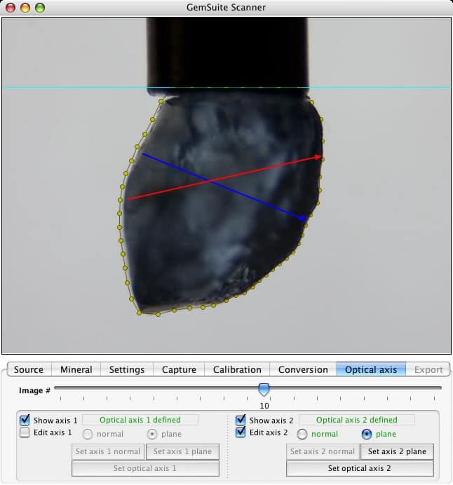
Screenshot 2 shows, for another captured image (90° further, turning around the dop axis), how the directions of the two axis are drawn after click-drag-releasing ye ole mowsie to define the "vectors".
I still have quite some work to do under the hood to make the transition between each displayed image (flattening the 3D "vector"). Uniaxial commands are essentially the same, but with only a single block of controls visible at the bottom left of the window.
The computing of the resulting 3D axis is already implemented and the data exported accordingly into Modeler, which will need a few objects added to be able to display both the scanning coordinate vectors (needed for proper transfer after the orientation of the rough is chosen) AND the optical axis.
Worth noting : the actual rough will have to be pre-oriented prior to dopping, mainly because the captured profiles are restrained to a single axis of rotation (one and a half for the "big" standalone gem scanner that I'll produce), and the profiles are captured with only half a turn of the stone around the dop (because it's enough to extract the whole geometry). This will give some constraints for scanning biaxials : namely, the two optical axis will need to be oriented as displayed here (one above the other, on the first image) to have the plane they form to be parallel with the camera sensor - ie you'll need to have them flat in one of the pictures. Hint : polariscope and a pair of thin-tipped black/red sharpies will certainly help to put dots on the rough, which will be visible in the pictures and will greatly simplify manually entering the points of the two optical axis. Well, same for an uniaxial, unless you have a clean crystal shape and the c is obvious, then you just have to dop on the a/b and go to town.
Thanks for your continued support guys, it means a lot to me! Żťüňä
Tom, a.k.a. Ludwig Von Sodabowski