January 4th, 2020 - Optical axis input : finale
Here's the final update about the optical axis input interface in GemSuite Scanner, that I just finished tonight. To sum it up :
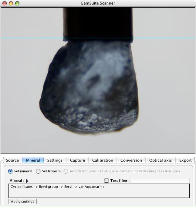
- you pick the material (picture 1)
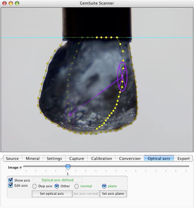
- if uniaxial, you either set the optical axis by defining the axis normal (circle with cross) by choosing the relevant image (which shows viewing down the optical axis) then the optical axis plane (viewing along said axis), by default the axis thus defined is horizontal, if it's tilted you click-drag to define a second point of the axis, fully defining it in 3D space (picture 2 shows an intermediary angle)
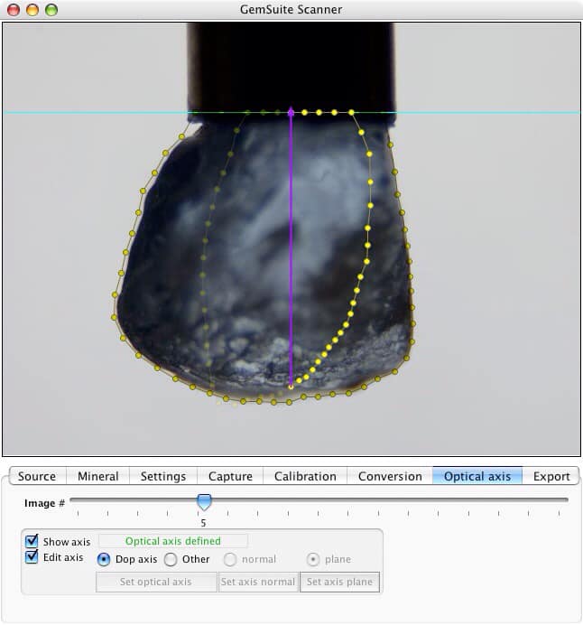
- a special case for uniaxials is when you're able to precisely dop along the optical axis, to avoid a transfer after scanning (if you're good enough at that game, then by all means go for it). In this case, the optical axis is defined with a dedicated button (picture 3)
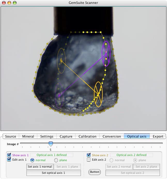
- for biaxials (picture 4), well you don't have a choice, for technical reasons (mainly to abide by the KISS principle) you have to dop the rough with the dopping axis in the same plane as the two optical axis, otherwise you can't enter them in the software. A good idea would be to put two colored dots of different colors on the piece of rough for each axis (to be sure to place them properly) and have the normals in the first captured image. Then, once you have defined both optical axis, you're good to go ahead and export the 3D model and optical axis data to Modeler.
I haven't implemented any kind of checking of the 2V for biaxials yet, but this will be "under the hood" type of work and won't show up much in the interface anyway. Yes, there will be a step-by-step video tutorial ₤■·ã
Next up : integration of the optical axis and mineral information into Modeler.
Thanks again for your interest and support!
Tom, a.k.a. Ludwig Von Sodabowski